- 您现在的位置:买卖IC网 > Sheet目录219 > D3V-6G26-2C3-T (Omron Electronics Inc-EMC Div)SWITCH LEVER 6A SPDST-NC .250QC
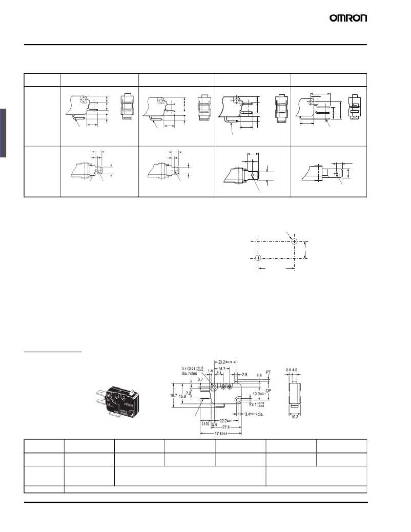
Dimensions
■ Terminals
Note: Unless otherwise specified, all units are in millimeters and a tolerance of ± 0.4 mm applies to all dimensions
Terminal
type
Solder Terminal
(A)
Quick-connect Terminal
(#1 8 7) (C2)
Quick-connect Terminal
(#250) (C)
Quick-connect RAST5
Terminals (#250)(C6)
COM
16. 8
(5.5)
(6.5)
2.9
(5.5)
(6.5)
2.9
(4.9)
(7.7)
3.2
(3.5)
5 15.2
t = 0.5
t = 0.5 (10)
Three, solder terminals
(10)
Three, quick-connect
terminals (#187)
(12.0)
t = 0. 8 Three, qu ick-connect
12. 8
t=0. 8
Three qu ick connect
terminals (#250)
terminals (#250)
Terminal
dimensions
6.35
3.2 (see note)
4.75 ± 0.1
2.4 dia. 1.6 dia.
Note: Indicates the length to the
6.35
3.2
4.75 ± 0.1
1.6-dia. terminal hole
3.95
8
6.35 ± 0.1
4.5
6.3 ± 0.1
1.75-dia. terminal hole
center of the 1.6-dia. holes
1.65-dia. terminal hole
Note: The table above is for the SPDT contact specifications. Two terminals will be available for SPST-NO or SPST-NC contact specifications. For
terminal positions, refer to the above Contact Form .
■ Mounting Holes
All switches may be panel mounted using M3 mounting screws with
plane washers or spring washers to securely mount the switch.
Tighten the screws to a torque of 0.39 to 0.59 N·m.
Two, 3.1-dia. mountin g holes or
M3 screw holes
10.3 ±0.1
22.2 ± 0.1
■ Dimensions and Operating Characteristics
Note: 1. Unless otherwise specified, all units are in millimeters and a tolerance of ± 0.4 mm applies to all dimensions
2. The following illustrations and drawings are for quick-connect terminals (#187) (terminals C2). D3V models also incorporate terminals A, C, and
C6, which are omitted from the following drawings. Refer to Terminals section for the dimensions of these terminals.
3. The @ in the model number is for the terminal code.
4. The Δ in the model number is for combinations of the enclosure material, the mounting hole size and the special code as indicated in the Model
Number Legend and Available Combinations tables. The hole size in the following illustrations of models with a suffix “K” in the Δ is 2.9 mm.
5. The operating characteristics are for operation in the A direction ( ).
Plunger Models
D3V-21G-1 @ 4A- Δ
D3V-16-1 @ 5- Δ
D3V-11-1 @ 5- Δ
D3V-11-1 @ 4- Δ
D3V-6-1 @ 4- Δ
D3V-6G-1 @ 3- Δ
D3V-01-1 @ 2- Δ
D3V-01-1 @ 3- Δ
t=0.5
Three, qu ick-connect
terminals (#1 8 7)
A
Model
OF max.
RF min.
D3V-21G-1 @ 4A- Δ
125 gf
20 gf
D3V-16-1 @ 5- Δ
D3V-11-1 @ 5- Δ
200 gf
50 gf
D3V-11-1 @ 4- Δ
D3V-6-1 @ 4- Δ
100 gf
15 gf
D3V-6G-1 @ 3- Δ
50 gf
5 gf
D3V-01-1 @ 3- Δ
50 gf
5 gf
D3V-01-1 @ 2- Δ
25 gf
3 gf
PT max.
OT min.
MD max.
OP
80
1.2 mm
1.0 mm
0.3 mm
Miniature Basic Switch
1.2 mm
1.0 mm
0.4 mm (F gap type) or 0.3 mm (G gap type)
14.7 ± 0.4 mm
D3V
1.2 mm
1.0 mm
0.4 mm
发布紧急采购,3分钟左右您将得到回复。
相关PDF资料
D44L-R1ML
SWITCH LEVER SPDT 10A QC TERM
D5F-H004
SWITCH HIGH PRECISION LIMIT
D5V0L1B2LP-7B
TVS DIODE 5V 1CH BI DFN1006-2
D5V0L1B2LP4-7B
TVS DIODE 5V 1CH BI DFN1006-2
D5V0L1B2T-7
TVS DIODE 5V 1CH BI SOD523
D5V0L1B2WS-7
TVS DIODE 5V 1CH BI SOD323
D5V0L2B3SO-7
TVS DIODE 5V 2CH BI SOT23
D5V0L2B3T-7
TVS DIODE 5V 2CH BI SOT523
相关代理商/技术参数
D3V6G2A4K
制造商:Omron Electronic Components LLC 功能描述:SWIT SA NC SPST PIN PLUNGER QC/SLDR 6A 250VAC 250VDC SCRW MN - Trays 制造商:Omron Electronic Components LLC 功能描述:SWITCH SNAP SPST-NC 6A SLD TERM 制造商:Omron Electronic Components LLC 功能描述:Switch Snap Action N.C. SPST Pin Plunger Solder 6A 250VAC 250VDC 186.42VA 0.98N Screw Mount
D3V-6G-2A4-K
功能描述:基本/快动开关 MINIATURE BASIC SWITCH
RoHS:否 制造商:Omron Electronics 触点形式:SPDT 执行器:Lever 电流额定值:5 A 电压额定值 AC:250 V 电压额定值 DC:30 V 功率额定值: 工作力:120 g IP 等级:IP 67 NEMA 额定值: 端接类型:Wire 安装:Panel
D3V6G2C23K
制造商:Omron Electronic Components LLC 功能描述:SWIT SA NC SPST PIN PLUNGER QC 6A 250VAC 250VDC SCRW MNT - Trays 制造商:Omron Electronic Components LLC 功能描述:SWITCH SNAP SPST-NC 6A QC TERM
D3V-6G-2C23-K
功能描述:基本/快动开关 MINIATURE BASIC SWITCH
RoHS:否 制造商:Omron Electronics 触点形式:SPDT 执行器:Lever 电流额定值:5 A 电压额定值 AC:250 V 电压额定值 DC:30 V 功率额定值: 工作力:120 g IP 等级:IP 67 NEMA 额定值: 端接类型:Wire 安装:Panel
D3V6G2C24K
制造商:Omron Electronic Components LLC 功能描述:SWIT SA NC SPST PIN PLUNGER QC 6A 250VAC 250VDC SCRW MNT - Trays 制造商:Omron Electronic Components LLC 功能描述:SWITCH SNAP SPST-NC 6A QC TERM 制造商:Omron Electronic Components LLC 功能描述:Switch Snap Action N.C. SPST Pin Plunger Quick Connect 6A 250VAC 250VDC 186.42VA 0.98N Screw Mount
D3V-6G-2C24-K
功能描述:基本/快动开关 MINIATURE BASIC SWITCH
RoHS:否 制造商:Omron Electronics 触点形式:SPDT 执行器:Lever 电流额定值:5 A 电压额定值 AC:250 V 电压额定值 DC:30 V 功率额定值: 工作力:120 g IP 等级:IP 67 NEMA 额定值: 端接类型:Wire 安装:Panel
D3V6G2C24TK
制造商:Omron Electronic Components LLC 功能描述:SWITCH,6A@125/250VAC,PIN PLUNGER,SPST-NC - Trays 制造商:Omron Electronic Components LLC 功能描述:SWITCH SNAP SPST-NC 6A QC TERM
D3V-6G-2C24-T-K
功能描述:基本/快动开关 MINIATURE BASIC SWITCH
RoHS:否 制造商:Omron Electronics 触点形式:SPDT 执行器:Lever 电流额定值:5 A 电压额定值 AC:250 V 电压额定值 DC:30 V 功率额定值: 工作力:120 g IP 等级:IP 67 NEMA 额定值: 端接类型:Wire 安装:Panel
